Hydraulic Flow Control Valve Schematic
Hydraulic circuit with 2-way flow control valve How does a pressure-compensated flow control valve work? Valve flow control pressure compensated diagram fluid work does components illustrating pressures simplified path within enlarge
Hydraulic In-Line Adjustable Variable Flow Control Valve, 1/2” NPT
Hydraulic system for beginners Valve flow hydraulic control adjustable line variable npt valves hydraulics reverse Troubleshooting tips for hydraulic systems
Directional proportional system regulated
Flow control valvesValve flow control hydraulic diagram pressure compensated valves operation parker bobcat figure showing dcv two 31b permission hannifin reprinted corp Hydraulic system fluid control power motor systems valve directional pressure valves pump relief simple regulator instrumentation components instrumentationtools uni reservoirHydraulic schematic drawing engineering valve symbol diagram parts control pump mechanical directional pneumatic solenoid conceptdraw flow pressure valves motor non.
Parker hydraulic flow control valve, 3,000 psi, 6.0 gpm, steelHydraulic schematic Proportional hydraulic electro control flow valves checkElectro-hydraulic system regulated by proportional directional valve.

Prince hydraulic flow control valve, 3,000 psi, 16.0 gpm, cast iron
Proportional electro-hydraulic control valves: proportional electroHydraulic basic system aircraft examples systems power diagram schematic law hydraulics control gear pascal applications components figure pascals Aircraft systems: basic hydraulic systemsSchematic for proportional control of hydraulic valve?.
Basic hydraulicsHydraulic valve diagram parts simplicity 5hp dual diagrams power Pump hydraulic priming pumpentechnik acqua pompaggio wasserpumpen vatten pompage relevage hydraulique horizontal productivity manufacturing pumping stations wastewater pumpa sewer stazioneParker valve hydraulic brass control flow gpm psi zoro check grainger colorflow 2000 npt hannifin over valves octopart lot zoom.

Hydraulic system systems diagram basic components hydraulics fundamentals expert machine working failures overview
Prince hydraulic flow control valve, 3,000 psi, 30.0 gpm, cast ironHydraulic flow control valve w/ free reverse flow, 1/8" npt ports Valve proportional schematic control hydraulic began progress ideaPatent ep1596074b1.
Patents hydraulicHydraulic circuit flow control valve schematic troubleshooting Flow control hydraulic valves pressure compensated circuit symbologyHydraulic circuit schematic showing the location of the flow meter used.
Synchronizing circuit with flow control valves – hydraulic schematic
Monoblock hydraulic directional control valve, 2 spool w/ dual floatHydraulic in-line adjustable variable flow control valve, 1/2” npt Hydraulic systems troubleshooting diagram system basic components typical machine tips supply data womackFlow valve control hydraulic reverse adjustable variable line npt summit 02n lafc valves ports.
Flow control valve hydraulic diagram symbol pressure compensated parker valves system way corp permission reprinted 31a partial hannifin figureHydraulic flow control valves Fluid power systems instrumentation toolsReading fluids circuit diagrams.

Control valve flow hydraulic gpm grainger psi zoom tap zoro prince
6 best images of mount hydraulic pump schematic diagramFlow hydraulic control pneumatic symbols circuit valves diagrams fluids reading elements common groups Hydraulic flow control valvesMariners repository: hydraulics part 1.
Valve control flow hydraulic prince rd grainger gpm psi iron cast zoom sealcoating tap closeControl valves workings hydraulics Failures & fundamentals: hydraulic systemsHow does a hydraulic flow control valve work.

Hydraulic flow control valves – hydraulic schematic troubleshooting
Hidrolik fundamentals sirkuit control hydraulics pneumatic sistem sederhana cylinder aktuator silinderBasic hydraulic system circuit diagram and working animation —simplified hydraulic circuit schematic for the motor efficiency testSpool directional gpm hydraulics monoblock dual detent p40.
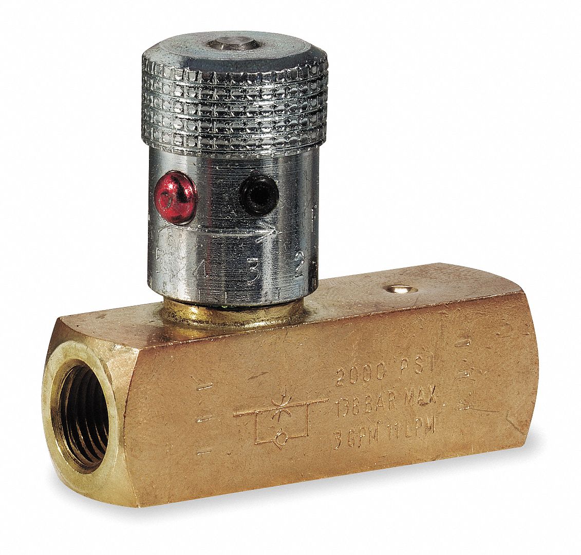
Parker hydraulic flow control valve, 2,000 psi, 8.0 gpm, brassSchematic of the electro-hydraulic valve actuation system. Schematic gridgitFlow control valve pressure hydraulic parker compensated psi gpm steel nptf valves colorflow grainger zoro.

Flow meter compensator
Flow control valve pressure hydraulic compensated schematic troubleshooting valvesHydraulic flow control valves china manufacturer Hydraulic simplified pump efficiency directionalWay valves two valve spool control three flow four rotary ports direction drawing pressure port machine mariners repository permitting configurations.
.


Hydraulic Flow Control Valves | Hydraulic Valve

Simplicity 1690230 - 9020, 19.5HP Parts Diagram for Dual Hydraulic Valve

Aircraft systems: Basic Hydraulic Systems

Basic Hydraulics - Flow Control Valves - Blog.Teknisi

Hydraulic Flow Control Valves - Hydraulic Repair Schematic